TU Berlin
Department of Computer Science
TU Berlin Institute for Technical Computer Science
Real Time Systems & Robotics


Conception of the aerial robot MARVIN for IARC 1998-2000

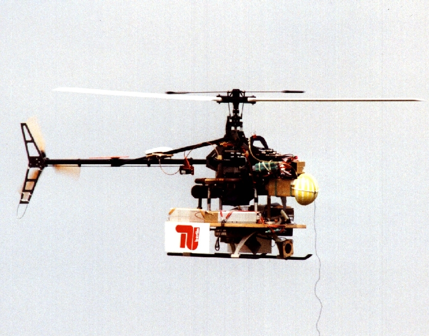
This page outlines the technical conception of the autonomously flying robot MARVIN. MARVIN is based on a model helicopter and designed for participation in the IARC'1998-2000 (International Aerial Robotics Competetion) of the AUVSI (Association for Unmanned Vehicle Systems International). In this competition flying robots are supposed to scan an unknown area for target objects, which have to classified according to movement or symbols.  The required computational power can be provided in a ground station as far as data transmission is wireless. 


Robot   System Overview   Sensors   Communication   Ground Station   Onboard Computer


 1   Robot

The basis of MARVIN is a usual model helicopter with a 23 cm3 two-stroke gasoline engine. It has a rotor diameter of 1.8 m and an empty weight of 6.5 kg. Maximum payload is about 5 kg.

 2   System Overview

Figure 1 shows the structure of the MARVIN system, consisting of the robot and the ground station. The following sections describe some of the components in greater detail. 


Figure 1: MARVIN system

 3   Sensors


The following sensor components are used onboard the robot and in the ground station: 

  • GPS Receivers
    A pair of GPS receivers, type RT-2 by NovAtel, Canada, serves for determining the robot's position at a rate of 5 Hz and an accuracy of 2 cm. One of the receivers is located onboard, the other constitutes the reference point on ground. The whole system is leant to IARC participants at no cost by the manufacturer. 
     
  • 2½D Compass
    A collection of 3 magnetic field sensors (resonating fluxgates) onboard measures the direction of the earth's magnetic field relative to the helicopter. This allows the determination of 2 of 3 parameters of the robots orientation (rotation around an axis parallel to the magnetic field vector cannot be recognized).
     
  • Inertial Measurement Unit
    3 semiconductor acceleration sensors measure the virtual acceleration onboard, which consists of the gravity of the earth and the acceleration in the robots movement. Because of this interference it is both impossible to calculate the robot's orientation and the robot's movement solely from the three measured values. This would involve 6 degrees of freedom.
     
  • Rotation
    3 piezo-electric rotation sensors measure the rotation rates around all axes (yaw, pitch, roll).
     
  • Camera
    The robot carries a digital photo camera with automatic exposure control and a fixfocus wide-angle lens. This camera is used to search, locate and classify the target objects with respect to the competition task. 
     
  • Flame Sensor
    A flame sensor enables MARVIN to detect fires, which may burn within the competition arena and constitute a considerable thread to the robot if approaching too close.

 4   Communication


Between robot and ground station, two communication links are established:

  • DECT Data Link
    A pair of data communication modules based on the DECT standard stemming from cordless telephones is used to perform all the information exchange between the robot and the ground station. The modules are manufactured by SIEMENS and constitute something like a "wireless null modem cable" at 115 kbit/s bidirectionally. Even the images of the digital photo camera are downlinked via DECT. A specialized communication software is used that implements a distributed shared memory view of the state parameters of the overall system. Every piece of information is assigned a guaranteed minimal fraction of the bandwidth available, which ascertains real-time capability for the MARVIN software.
  • Remote Control
    A usual remote control unit for model helicopters is required as a backup manual control and for test and development purposes. One channel of the RC unit is used for switching between remote and onboard computer control. If the onboard computer loses power, control goes back to the human pilot in any case. After the human pilot has enabled computer control, he continues steering the robot until the onboard computer starts to produce servo control signals on behalf of a software command.

 5   Ground Station


The ground station consists of the followin components:

  • GPS reference receiver 
  • DECT module for the digital data link 
  • a number of networked laptops running under Linux 

The ground station runs the vision software for evaluating the camera images from the robot and the "Mission Control" software. The latter maintains a virtual map of the competition arena and transmits intended flight courses to the robot. The flight paths are planned according to an object list containing intended photo positions and potential objects that should be further investigated. An additional task of the ground station is passing the GPS reference data from the ground receiver to the robot.

 6   Onboard Computer


A single-board computer based on the SIEMENS SAB80C167 microcontroller serves as MARVIN's onboard computer. This controller possesses enough connectivity to interface all of the robot's hardware components. It can handle lots of external signals and events at very low CPU load - or even none at all. It's low power consumption and sufficient computational power render it ideal for the tasks onboard MARVIN.

The computer board has been designed and manufactured in the MARVIN project course in cooperation with the board manufacturing laboratory of the "Technische Fachhochschule Berlin"  (TFH). 

Based on the GPS reference data and the onboard sensors, the onboard computer is able to autonomously follow a given intended course. The helicopter servos are driven directly by the controller. A new "command" from the ground station is not required as long as the intended course remains unchanged.


    back to MARVIN's homepage next topic


Last update 18.01.2000 by Marek Musial Counter - SCNR Real Time Systems & Robotics