Department of Computer Science |
 |
Institute
for Technical Computer Science |
MARVIN MarkII Hardware
Department of Computer Science |
|
Institute
for Technical Computer Science |
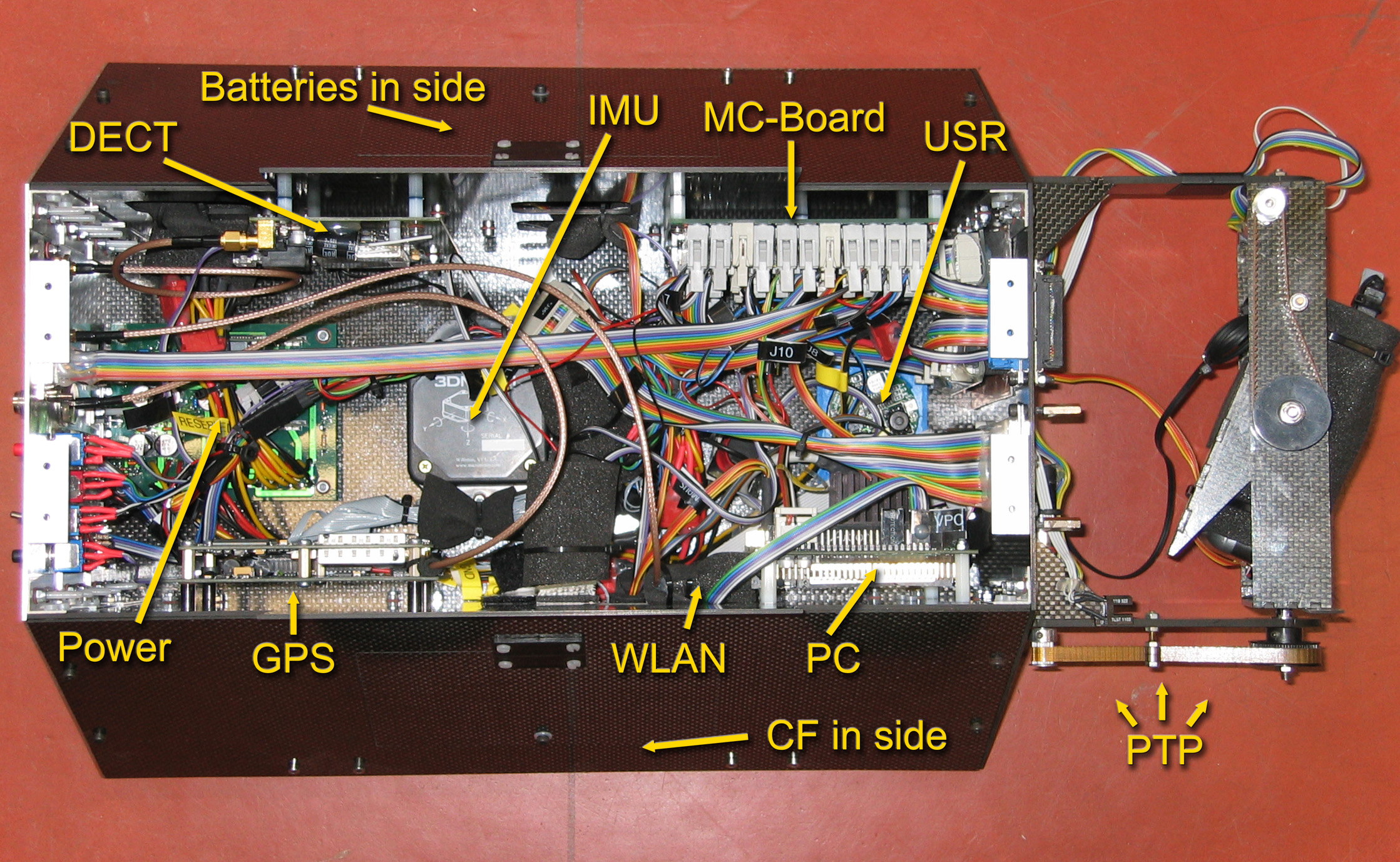 |
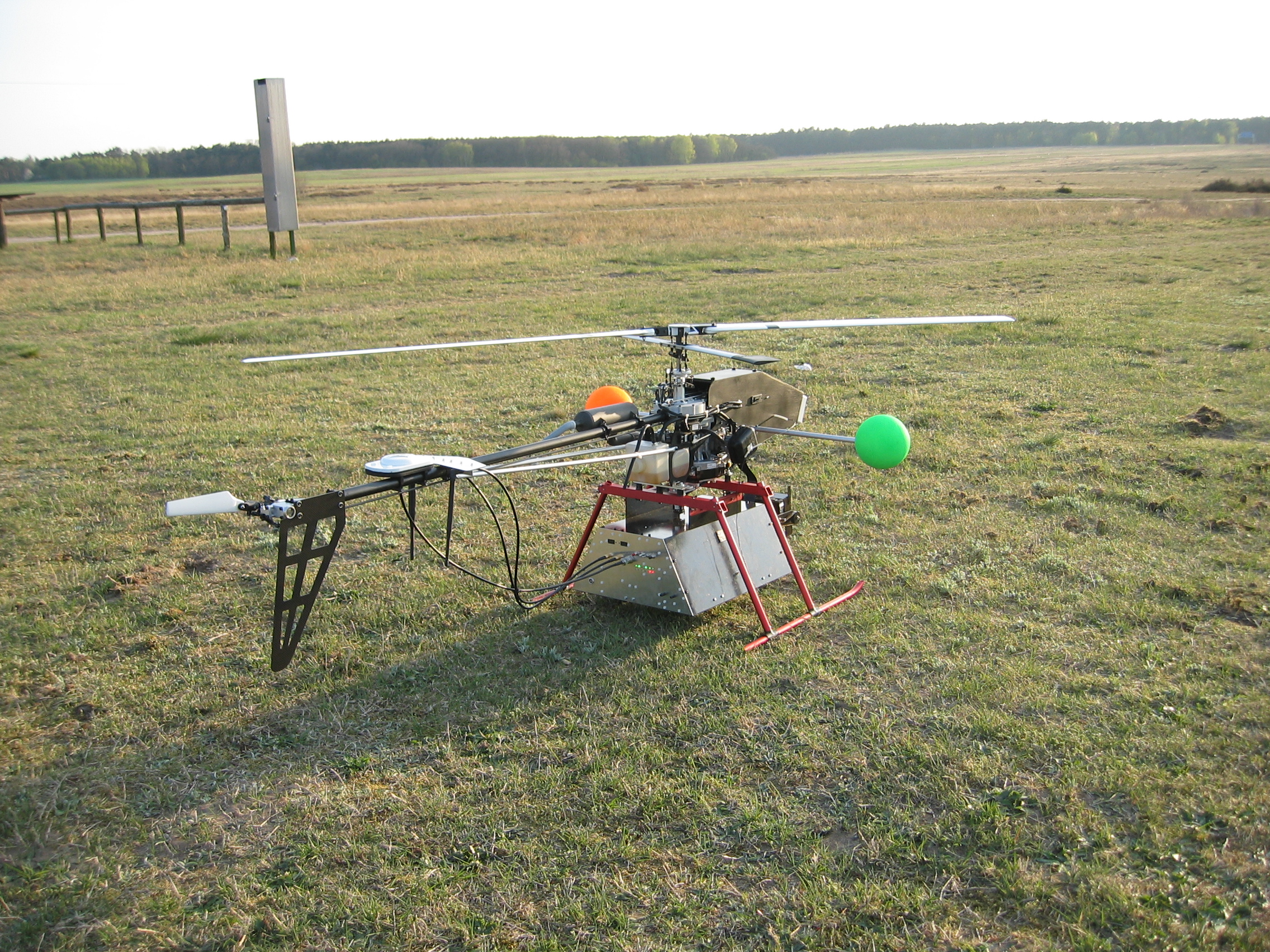
While it is true that there is some space left in the helicopter's black nose-case the decision was taken to go for the more flexible and comfortable approach (when it comes to development and maintenance) to attach a box beneath the helicopter that can contain a variable number of computer systems, sensors, powersupplies and batteries. Another benefit of this design is the easier replaceability of standard helicopter parts in case of a rough landing/crash. The box itself is completely cut from carbon fibre sheets besides one aluminimum side that is used for most connectors and as power supply unit's heat sink. In the above picture you can see most components of the MarkII sytem.
 The
MarkII uses indirectly a DECT
(Digitital Cordless European/Enhanced Telephone) OEM
module by Hoeft+Wessel for a transparent serial link for
communicating with the base station. To ease the integration
an end-user product was used. The good thing about this DECT
modem is that they come including an external antenna connector
and an own power supply that presumably fulfils all the specification
of the OEM module. Therefore it can easily be integrated into
the box.
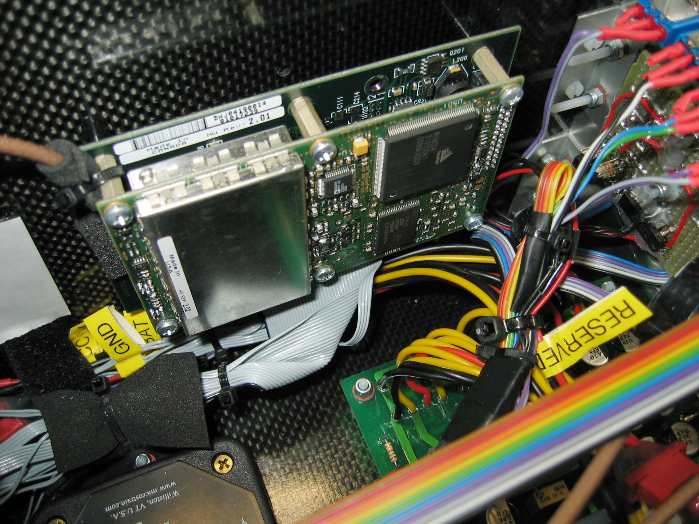
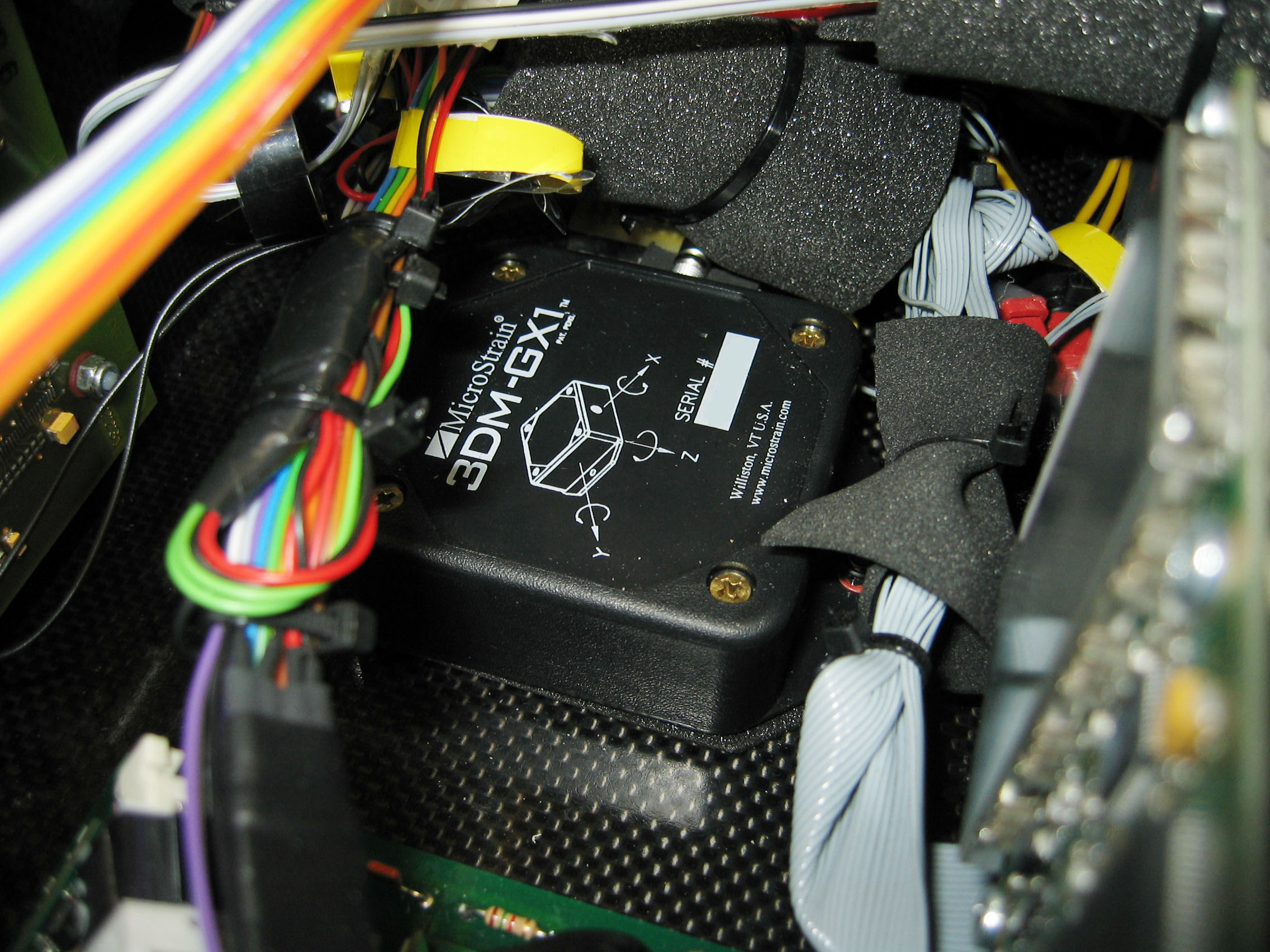 The box in the above picture shows an IMU (Inertial Measurement Unit) GX1 from Microstrain. This IMU integrates all needed sensors (rotation, acceleration and magnetic in 3D) and interfaces the microcontroller via RS-232. While the integration of all these sensors in a single device seems a very nice idea at first glance it turned out that for MarkII it was not possible to find a mounting place that was suitable for all the sensors at the same time. The accelerometers and rotational sensors are best placed decoupled below the center of mass of the helicopter while the magnetic sensors are heavily disturbed by the two-stroke engine's ingnition system (induction coil) and are best placed as far away as possible. In Marvin's case "far away" is the helicopter's tail section. So it was necessary to add a compass to the Microstrain when it was mounted as in the picture above or (as done on the second helicopter) to use the micostrain as compass only (mounted on the tail) and use anoter IMU in the box. Since the first Marvin used custom made IMUs and custom made compasses some of them were still around and were added as necessary.
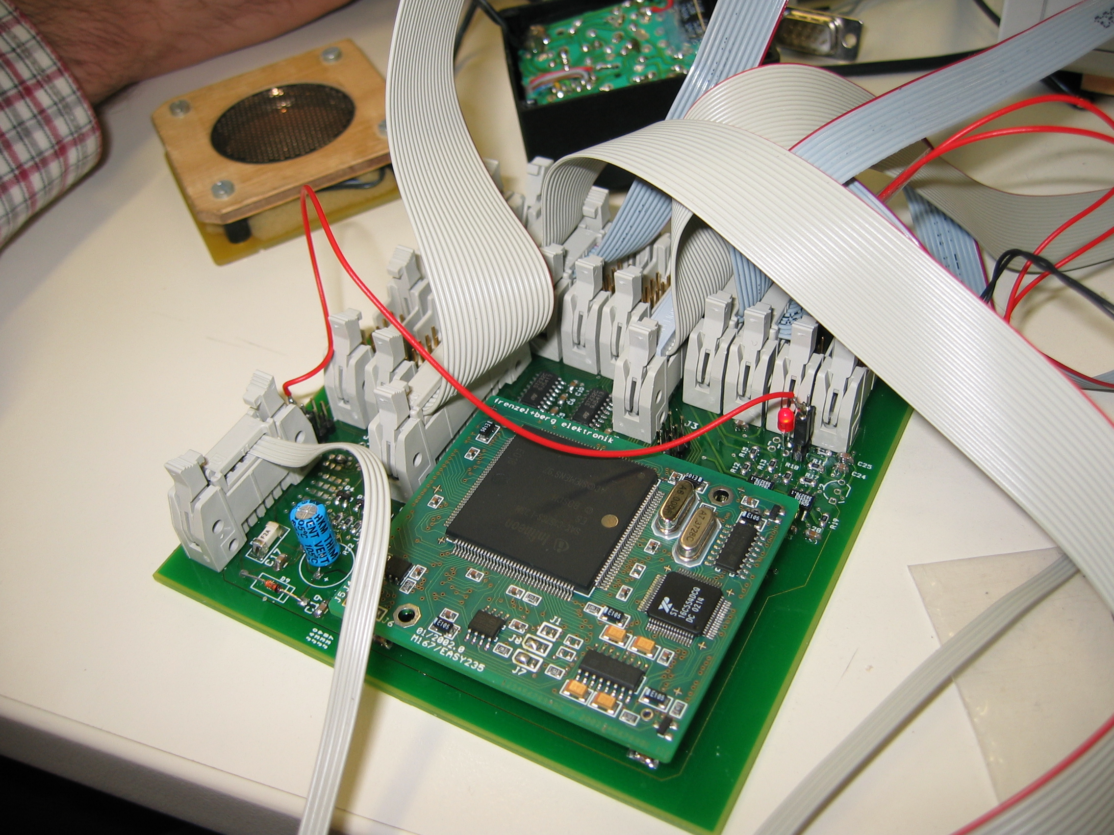 Heart of the system is the custom made MC-Board that contains an integrated Infineon C167 microcontroller module by Frenzel+Berg, some additional stuff for temperature and voltage monitoring and a lot of lockable connectors. The C167 is a 16-Bit microcontroller of good connectivity including Capture/Compare-Units, AD-Converters and GPIO. The Frenzel+Berg module comes with external Flash, external RAM and 4 additional serial ports.
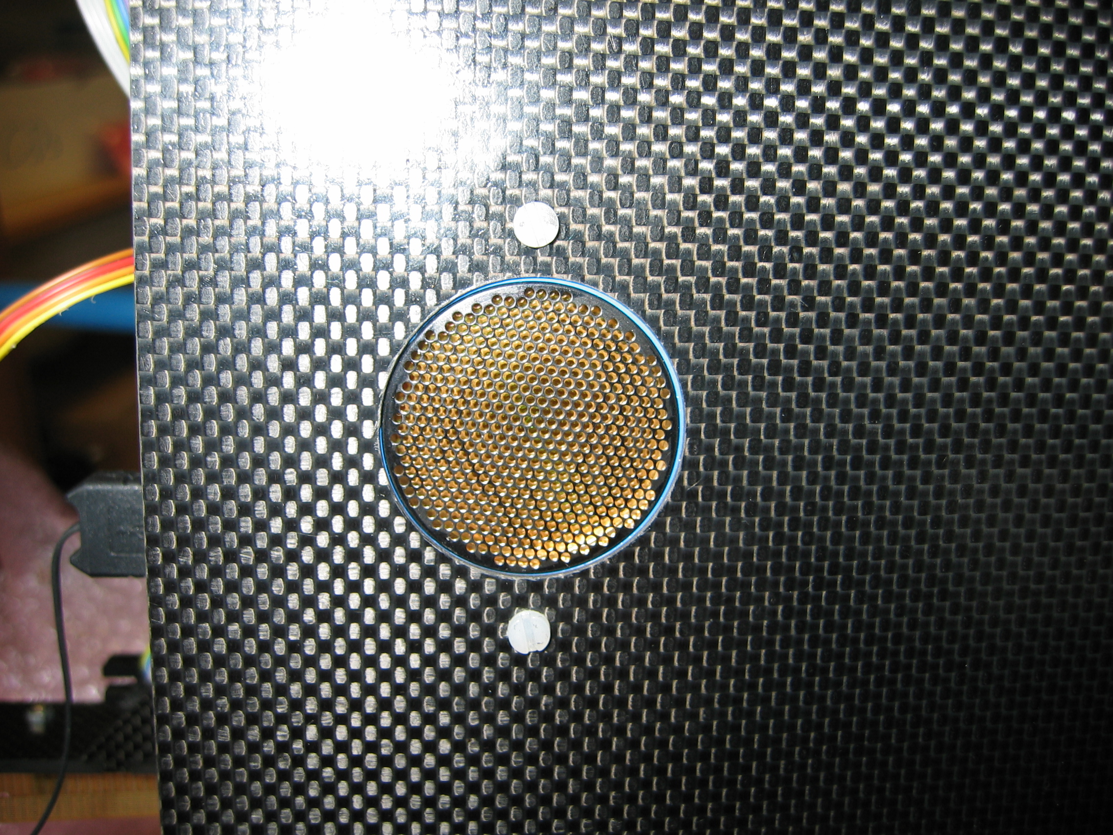
 Directly integrated into the base plate of the box is an USR (ultrasonic rangefinder) facing downwards. This USR is also a highly integrated sensor module by SmartSens and is mainly used to detect the ground during autonomous landings. There are also four high-bright red LEDs in the base plate. These are used to signal that the helicopter is in autonomous mode and to give some feedback about the current flight mode (i.e. helicopter turning, hovering, start flying).
 The GPS (Global Positioning System) is a high accuracy system OEM-4G2L by Novatel which came originally in a Flexpak enclosure. The GPS as integrated in the box still uses the Flexpaks interfacing and power supply board. This GPS is used in differential mode accompanied by a second, older Novatel receiver (OEM-3) on ground. The second existing MarkII helicopter is also using the older OEM-3 model. Both GPSs have a similar accuracy of 1 cm CEP while the OEM-4 has an maximal position update rate of 20 Hz and the OEM-3 of 5 Hz. The Marvin system uses 5 Hz or 10 Hz depending on the available rate.
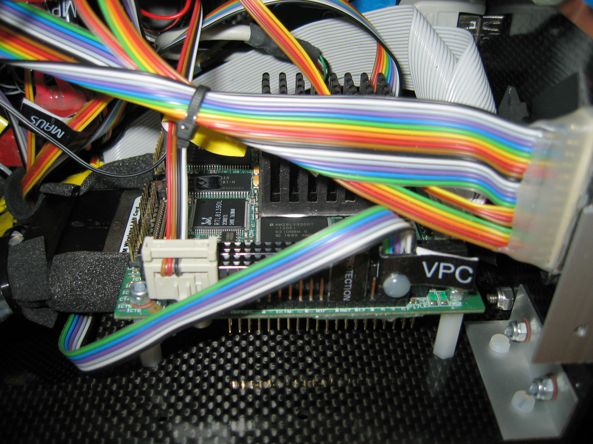 The PC is a PC-104+ compliant, embedded National Semiconductor Geode system-on-chip (now property of AMD) SB-i686 by Compulab. It is running embedded Windows XP to drive the digital still camera that is connected to it via USB and boots from a compact flash card that is attached via IDE. In its pc-card slot is a wireless LAN card for image transfer to the base station, but the wireless LAN can also carry all data transferred from the MC to the base station in case of a DECT failure. The
PC on-board helicopter 1 is not necessary for autonomous
flight. Actually, the PTP (pan-tilt-platform) and the PC including
wireless LAN (WLAN), CF (compact flash drive) and the actual
camera mounted in the PTP are payload and build the image acquitistion
system (see next page). This is also true for the flame
sensor that is hidden in the white box at the front most
part of the helicopter as it can be seen on the helicopter pictures
(see below). 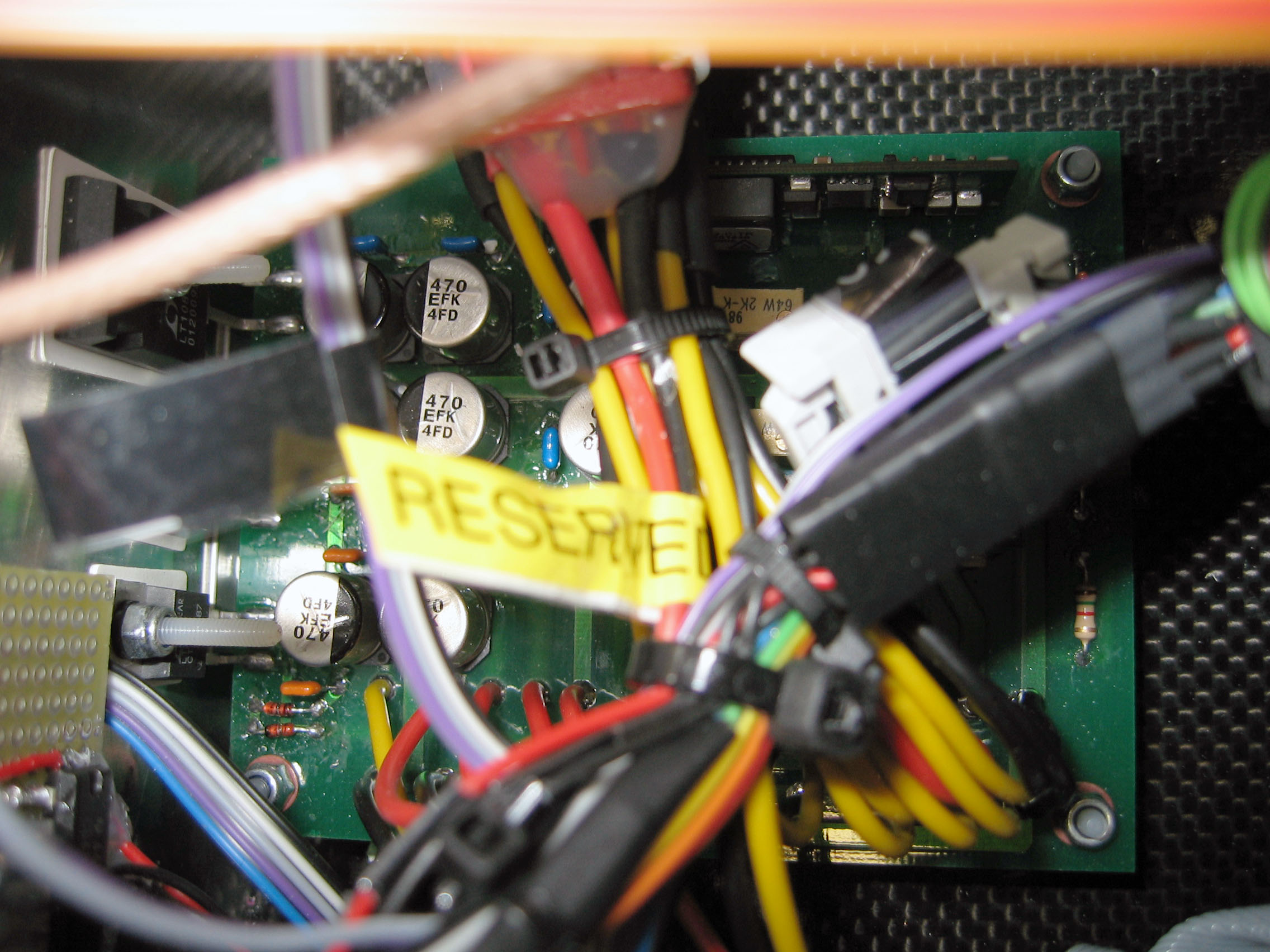
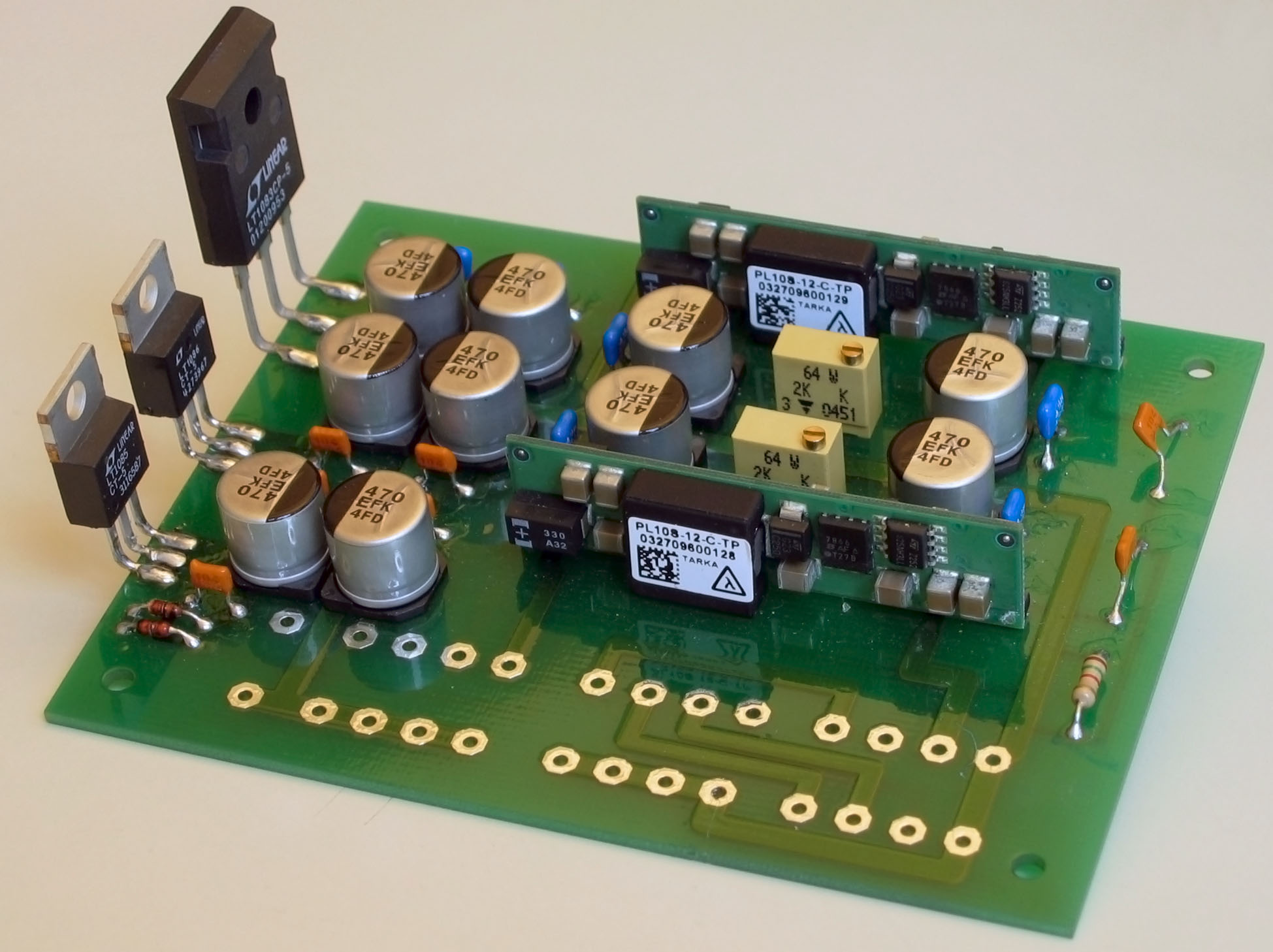 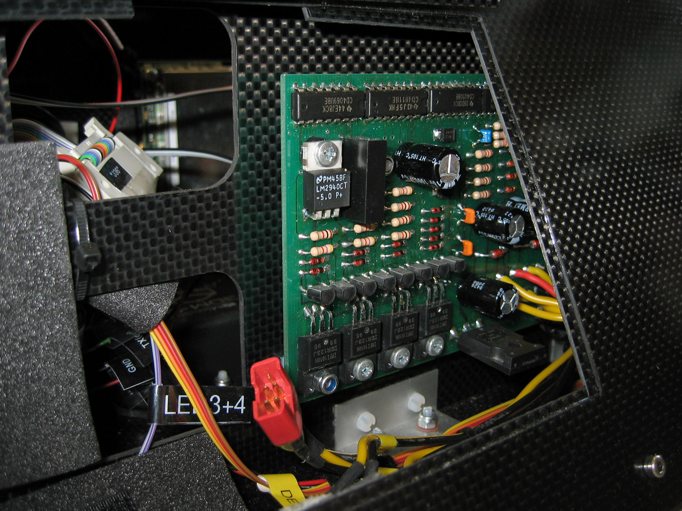 Sitting at the aluminium sheet is the Power supply unit that takes a variable voltage from the batteries and converts it to 5 V and 3.3 V using mostly DC-DC-Converter modules PL10S made by Lambda. These modules work nicely and produce a well regulated, comparatively low-noise output suitable for all the digital systems. Additionally there are very low-noise linear regulators for analog systems ecspecially sensors and AD-converters. On the second picture is a board which sole purpose is to select the strongest of up to 3 attached batteries or switch to an external power supply if connected. The complete Marvin system is powered with these boards using lithium-polymer rechargables from Kokam. A three cell 3 Ah, 200 g battery pack powers the system including the image acquisition system for at least 90 minutes. Not
inside the box is the DDS-10 RC-receiver made by ACT.
Since the receiver is used by the helicopter for manual remote
control it is installed in the helicopters nose and powered by
the helicopter battery. This receiver has an astonishing set
of unique features and one of them makes it necessary to mention
the receiver also here as part of the autonomous equipment. ACT
calls this special functionality DSL-S (Diversity Synchro-Link
System). The basic idea is that this link (RS232 actually) can
be used to connect two of their receivers to set-up a diversity
reception for manual remote control. The two receivers are
then simply exchanging the information they received. This may
be used for antenna diversity and frequency diversity or as a
master-slave setup for teaching remote control. The latter case
is very interesting since one can make use of it for an autonomous
system. In the MarkII setup the microcontroller connects to the
receiver via this link being the slave where the remote control
is the master. Using this connection the microcontroller can
read all data that is received from the remote control and, when
allowed via a teaching switch at the remote control, the microcontroller
can also control all helicopter servos by sending the same type
of datagrams to the receiver. The receiver's design is quite
robust, it falls automatically back to remote control when the
microcontroller stops sending datagramms but it also keeps on
using the microcontrollers data when the remote control is failing,
getting out of reach or just switched off. 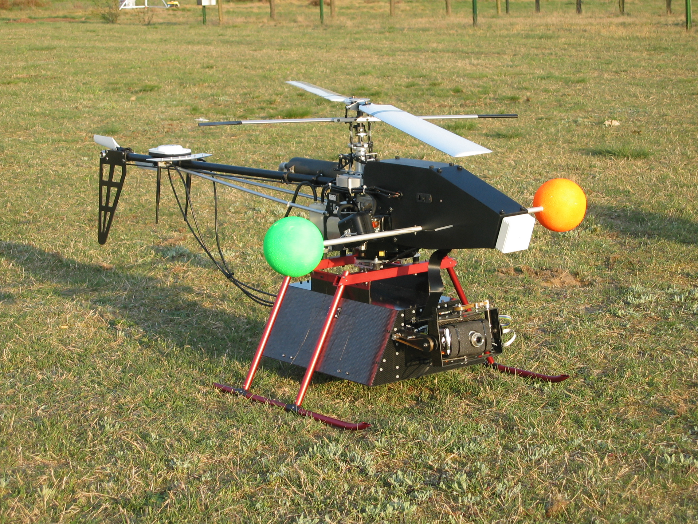
 |
Next
Previous - Top - Home