Department of Computer Science |
 |
Institute
for Technical Computer Science |
MARVIN MarkII System Design
Department of Computer Science |
|
Institute
for Technical Computer Science |
       Diagram
      for a complete autonomous MarkII system including ground base
      and the optional image acquisiton system
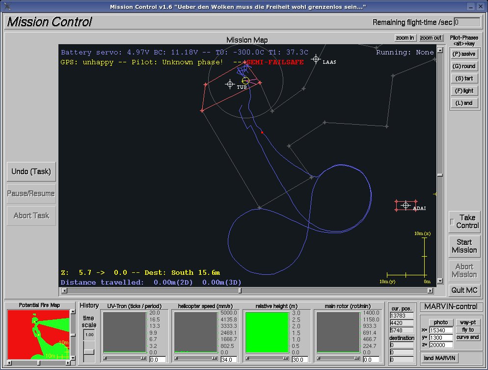
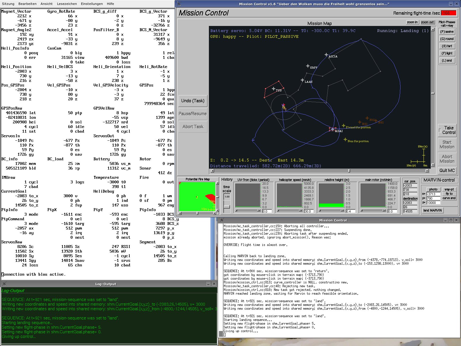
Changing a remote-piloted helicopter to an autonomous UAVTo be able to fly a model helicopter autonomously you have to steer the helicopter automatically. The automatic steering can occur on any point between in-front-of-the-remote-control to just-before-the-servos. Due to automatisms mentioned in the preceding page, the decision for the original Marvin system was to go to the lowest level and put a microcontroller on the helicopter that generates the servo signals directly and is sparing out any remote control automatisms. The hardware design makes it possible to switch from remote controlled to autonomous operation during the flight in progress. The decision to switch between the two modes is made by the microcontroller's program but can be overridden by a lever on the remote- control to switch to remote-controlled flight even if the microcontroller do want to behave otherwise. Switching back to manual flight is always the last resort if something goes fundamentally wrong with the helicopter. Since Marvin is using independent batteries for the microcontroller and the remote control receiver and servos, the hardware falls back to remote-controlled flight if the microcontroller is running out of battery. In addition the microcontroller is able to monitor the signals that are sent to the servos during a remote-piloted flight and they can be logged. Originally all the above mentioned servo and receiver interfacing was done using dedicated custom-built hardware and the microcontroller directly. Finally, this was no longer necessary since there is available a receiver system that comes with this functionality built-in (see next page). To give the full meaning to the word autonomy the MarkII can even start its engine autonomously using the electric on-board starter which is also controlled by a receiver output. What is needed for autonomous flight?The microcontroller is also the only CPU on board the helicopter uses for autonomy. Therefore, all the needed sensors are connected to it and it runs all programs for control purposes, sensor data acquisition and calculations. To fly the helicopter autonomously the control program in the microcontroller needs information about the current position and the orientation of the helicopter. Additional information about the main rotor rpm is needed to regulate the throttle and a sensor for the distance to the ground for landing purposes. The Marvin system uses a Differential Global Positioning System (DGPS) to get accurate and frequent position information and a combination of three rotational speed, three acceleration and three magnetic field sensors for movement detection. A fusion algorithm is used to calculate the helicopter's attitude. The main rotor rpm is detected magnetically at the rotor axle and the distance to the ground by an ultrasonic sensor. Each of these sensors is directly connected to the microcontroller. To add the D to GPS a stream of correction data from a base station is needed, in case of Marvin it is embedded in the normal data transfer between the base station and the helicopter and then transferred through the microcontroller to the on-board GPS. On the ground...there is a base station consisting of a bunch of tools and programs. The salient program is the Mission Control, mainly because it has a GUI. The first picture below shows Mission Control program (MC) which represents the base software's user-view. This program can be used to plan and survey a mission flight including definition of waypoints to fly to and giving the command for start and abortion if necessary. It can display some basic digital map data, the helicopter's position and heading as well as the flown path. There are also some status informations and flight parameters. Behind the scenes the MC sends atomic commands to the helicopter systems that then are executed indepedently. Ending the MC does not end the autnomous flight. Since the data displayed by the MC is not sufficient for development the typical base station setup looks more like on picture two where the MC is accompanied by a numeric display of the most interesting data while the rest is just written to a log-file for later analysis.
|
Next
Previous - Top - Home
Contact persons:
Dipl.-Ing. Volker Remuß (E-Mail) or Dipl.-Inform. Uwe Wolfgang Brandenburg